Tag: water-leak

Posts about water leak on Lansen aluminum windows and doors.

  • Curtain Wall Water Testing: Mock-Up and Field Tests

    Curtain Wall Water Testing: Mock-Up and Field Tests

    “Curtain wall water testing” covers three different activities that are routinely confused with one another: a laboratory test of a specimen, a mock-up test of the job-specific assembly, and a field test of the wall that was actually installed. They are ordered, witnessed and interpreted differently, and each proves something the other two cannot. A specification that asks for water testing without naming which one usually buys the cheapest of the three and misses the risk that matters.
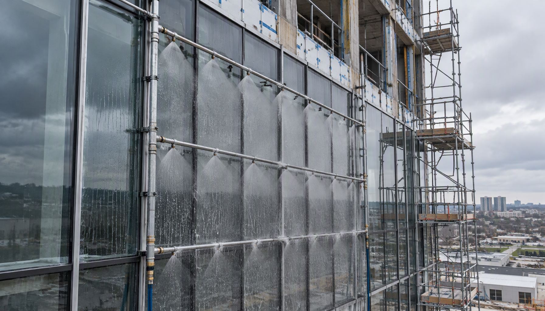
    Field water test of an installed curtain wall using a spray rack mounted on the exterior face of a building under construction

    Three Water Tests That Are Constantly Mixed Up

    The first distinction is between a test method and a performance requirement. ASTM E331 is a static water penetration test method; ASTM E1105-style procedures expose an assembly to water while the test pressure is cycled, which is closer to what wind-driven rain actually does. Both measure behavior on a specimen under defined conditions; neither is a rating a supplier can attach to every size and detail on your building.

    Field procedures are a third thing again. AAMA 501.2 is a voluntary industry procedure for checking installed window wall, curtain wall and storefront assemblies for water leakage using a hose or a mounted spray rack, and AAMA 503 supplements that approach with a defined field sequence — visual inspection followed by hose or spray-rack exposure, with guidance on what to do about water that is observed. These are checks on the finished installation, not a laboratory determination of a system’s capacity.

    Test StageWhat It IsWhat It Can Prove
    Laboratory test of a specimenA defined assembly tested to a stated method under controlled pressureHow that tested configuration behaves; the basis of a performance claim
    Mock-up or prototype testThe project’s own design, fabricators, sealants and interface details built and testedWhether this project’s specific assembly and detailing holds water
    Field test of the installed wallHose or spray-rack exposure on the completed installation with interior observationWhether the wall as built and as installed leaks, including workmanship

    The FGIA standards resources are where to confirm which document a specification is actually invoking, rather than quoting a designation from memory.

    Mock-Up Testing: The One That Catches Detailing Errors

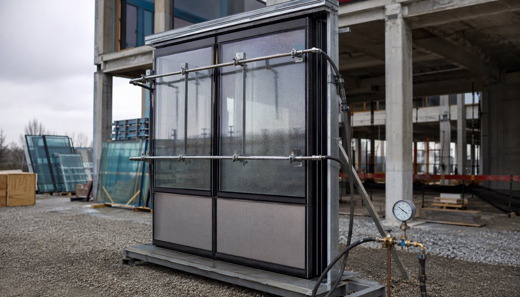
    A mock-up is the project’s assembly, not the brochure assembly. It should contain the conditions that cause field problems: a sill or threshold detail, a head condition, a movement joint, an opaque spandrel panel zone, a mullion cap run, and at least one interface with the building structure. If it omits the interface conditions, it tests the part that almost never leaks.

    On a curtain wall package, the two questions that decide the program are which system family is being built and who is fabricating it; the system families are defined in curtain wall system types, and the vendor-side evaluation in choosing curtain wall fabricators. Two sequencing points are worth enforcing. First, the mock-up should be built by the same crew, with the same sealant, substrates and primer sequence that will be used in production, or its result says nothing about production. Second, the mock-up should be inspected and tested before the permanent wall is fabricated, so that a correction costs a detail drawing rather than a demolition.

    Shop testing controls the environment and catches fabrication problems; an on-site mock-up additionally exposes erection and interface conditions. Where tolerances are tight the assembly route matters too — the difference between site-built and factory-built systems is dealt with in stick vs unitized curtain wall.

    Field Testing the Installed Wall

    Field testing is a workmanship audit performed with water. It examines what no laboratory specimen contains: field-tooled sealant joints, cap pieces that did not seat, fasteners that over-compressed a gasket, blocked or omitted drainage, and damage from other trades.

    What has to be agreed before the first nozzle goes on the wall:

    • Scope and sampling. Which elevations, what proportion of the wall, and which high-risk locations go first — corners, sills, movement joints and interfaces with rooflines and balconies.
    • Test pressure and duration. Stated in the procedure and applied consistently; ad-hoc hose work at unspecified pressure produces a result nobody can interpret.
    • Observation and documentation. Who watches the interior face, how a wetted area is recorded, and how pre-existing wetness is told apart from water admitted during the test.
    • Remediation and re-test. What happens after a failure: correction, sealant re-application with adequate cure time, then a re-test of the corrected area — not a punch-list note.

    Run it while the interior is accessible and clean enough to observe. Late testing over a finished interior, with protective film still undisturbed, is the most common reason a genuine leak gets written off as condensation.
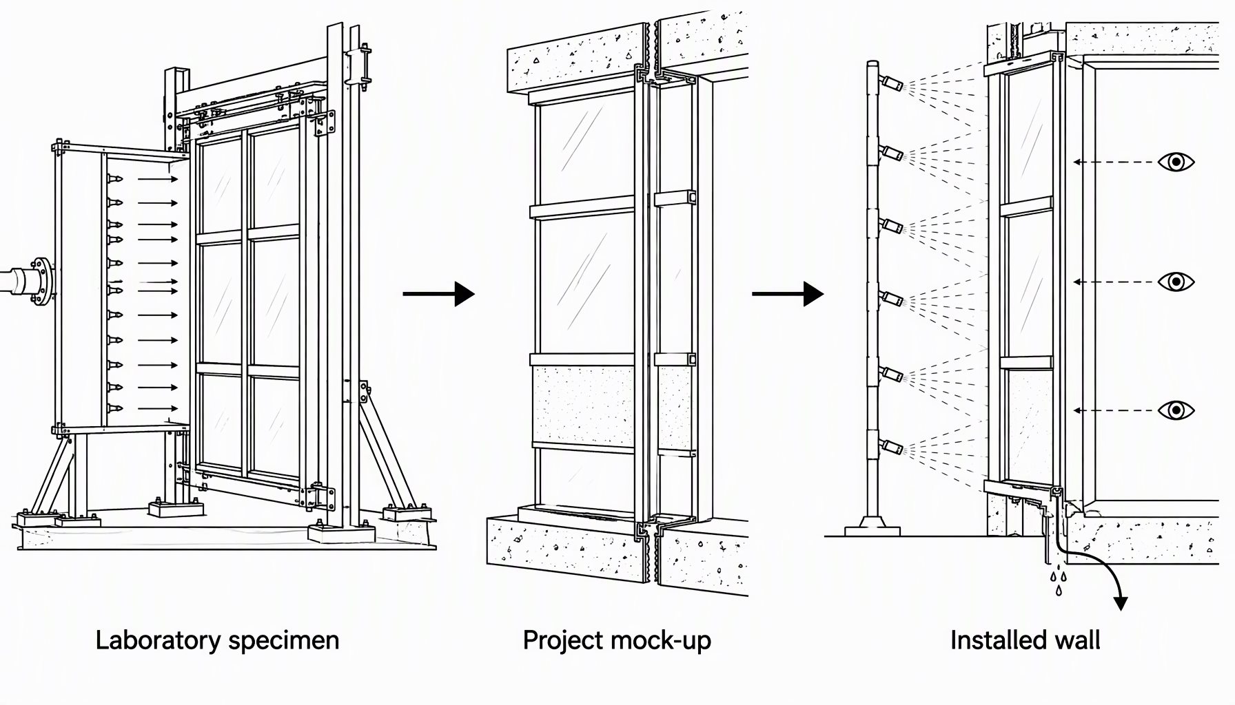
    Line drawing of a three-stage curtain wall water test program: laboratory specimen, project mock-up and installed wall with spray rack and interior observation points

    Curtain wall mock-up panel erected on site with a spray rack, supply hose and pressure gauge connected for water leakage testing

    What a Water Test Cannot Tell You

    A test report is a statement about a specimen. Performance is configuration-dependent: mullion spacing, glass size and weight, panel build-up, anchor layout and interface details all change the load path and the movement a joint must absorb. A result for one specimen does not automatically prove performance for every size or configuration on the project.

    The same caution applies to the paperwork. A test report, a certificate, a declaration of conformity and a code approval mean different things, and buyers routinely accept the wrong one. The distinction is laid out in our explanation of NFRC, AAMA, ENERGY STAR and impact ratings; for water performance specifically, the useful question is which method was used, on what specimen, in what configuration, and with what observed result.

    A dry test also does not mean a dry wall in perpetuity. Water management in a drained rainscreen assembly is a design property — the cavity, the drainage path and pressure equalization govern how much water passes the outer line and how fast it leaves. Field testing checks whether that design survived production; it does not replace it. The construction side of that is covered in curtain wall insulation, where the cavity and drainage layers are described.

    Where Curtain Wall Water Testing Finds the Real Failures

    Failures found in field testing cluster at a small number of locations, and they are almost never in the middle of a glazed bay.

    Location Found WetUsual Root CauseEvidence Worth Demanding
    Sill and threshold lineDrainage omitted, blocked or crossed by a sealant application; end caps unseatedDrainage detail as drawn and as built, with a cleared path
    Head and slab-edge interfaceMovement joint sized for the wrong total movement; incompatible substrateMovement calculation and sealant compatibility record
    Vertical mullion capsCap bridging, missing or under-compressed gasket at the cap lineGasket compression specification and inspection photo
    Opaque panel perimeterBack-pan sealing discontinuity at the panel edgePanel-edge detail and the mock-up result for that zone

    An interior wet surface is not always admitted water: condensation on a cold bridge is routinely misread as a leak, and the two have different remedies. The window-side versions are explained in condensation inside double glazing, and in why aluminum windows leak.

    What the Model Code Adds

    The model code treats an exterior wall as an assembly — weather resistance, the water-resistive barrier behind cladding, and performance as tested and evaluated — so water performance is not purely a voluntary industry matter. The provisions sit in IBC Chapter 14 on exterior walls, and the broader code library at ICC codes and standards is the wider reference library. Which edition binds your project is a local question for the authority having jurisdiction, not something to assume from a datasheet.

    Which Water Test Program Fits Your Project

    Project RequirementRecommended ChoiceWhy
    Standard mid-rise, repetitive assemblySystem documentation review plus a project mock-up and a sampled field testMock-up catches the detailing, field test catches the workmanship
    Complex geometry, tight tolerances or heavy wind exposureFull mock-up with the real interface conditions, tested before fabrication releaseCorrections are cheapest while they are still drawings
    Buyer needing to compare two biddersIdentical language in the specification for stage, method, pressure, sampling and re-testOtherwise the bids are not for the same wall

    Frequently Asked Questions

    What is curtain wall water testing?

    Controlled exposure of an assembly to water, usually sprayed and often with pressure cycling, to see whether water reaches the interior side. The term covers laboratory testing of a specimen, mock-up testing of a project assembly and field testing of the installed wall — three activities with three purposes.

    Is a laboratory water test the same as a field test?

    No. A laboratory test characterizes a defined specimen under controlled conditions; a field test audits what was actually fabricated and installed — sealant joints, anchorage, drainage clearance, damage from other trades. A project normally needs the field test even with excellent laboratory data.

    Does ASTM E331 give a curtain wall a rating?

    It is a static water penetration test method, not a rating. A method tells you how the measurement was made; it does not by itself establish a performance level for your configuration, and a report should not be summarized as a product rating.

    What is AAMA 503 used for?

    It is an industry field procedure that supplements hose and spray-rack style testing of installed assemblies with a defined sequence and remediation logic — inspect, test, correct, re-test. It is used to establish whether the installed wall performs, not to characterize a system’s laboratory capacity.

    How much of the installed wall should be field tested?

    A project decision that belongs in the specification, weighted toward high-risk locations — sills, head conditions, movement joints, corners and building interfaces — rather than spread evenly across the flattest, safest bays.

    Does curtain wall water testing prove energy performance?

    No. Water penetration and thermal performance are separate properties measured by separate programs, and an energy rating label from NFRC is not evidence about leakage. Each needs its own documentation.

    Can a wall pass a field test and still leak later?

    Yes. A test audits a point in time. Blocked drainage after handover, joints beyond their design range, later trades penetrating the assembly and gasket compression set all change the result, which is why drainage access and inspection belong in the maintenance plan.

    Who should witness the test?

    Someone with authority to stop work on a failure — the specifier, the consultant or the client’s representative — with observations recorded as they are made. A test witnessed only by the installer’s own team produces a record nobody outside can rely on.

    Get the Test Program Right Before Production

    If your project needs a curtain wall package reviewed for water test scope — mock-up content, field test procedure, sampling, acceptance criteria and the remediation path — send us your drawings, the elevation schedule, the site conditions and the performance requirements. We can review the test program against the assembly design before fabrication is committed — reach us through the contact page.
  • Drip Cap vs Caulk: What Keeps Water Out of a Window

    Drip Cap vs Caulk: What Keeps Water Out of a Window

    A drip cap and a bead of sealant solve the same problem at a window opening in opposite ways, and the drip cap vs caulk decision comes down to that difference. A drip cap is a shedder: it intercepts water running down the wall above and throws it clear of the head, so the water never reaches the joint. Sealant is a seal: it closes a joint water has already reached, and holds only while bonded to both surfaces. One works by geometry and gravity; the other by adhesion.

    That difference decides where each belongs: the drip cap at the head, integrated with the weather barrier and cladding; sealant at joints that must move and at terminations a shedder cannot cover. Neither substitutes for the other. A seal cannot replace a missing shedder, because it would then be holding back a stream rather than closing a gap, and a drip cap cannot seal a joint, because a shedder is deliberately open.

    The drip cap vs caulk confusion is expensive. A head caulked three times in ten years is usually not a maintenance problem but a missing shedder, and the recurring cost is the symptom. What follows covers choosing, specifying and inspecting the right component, not the causes of leakage — those are covered in why aluminum windows leak.

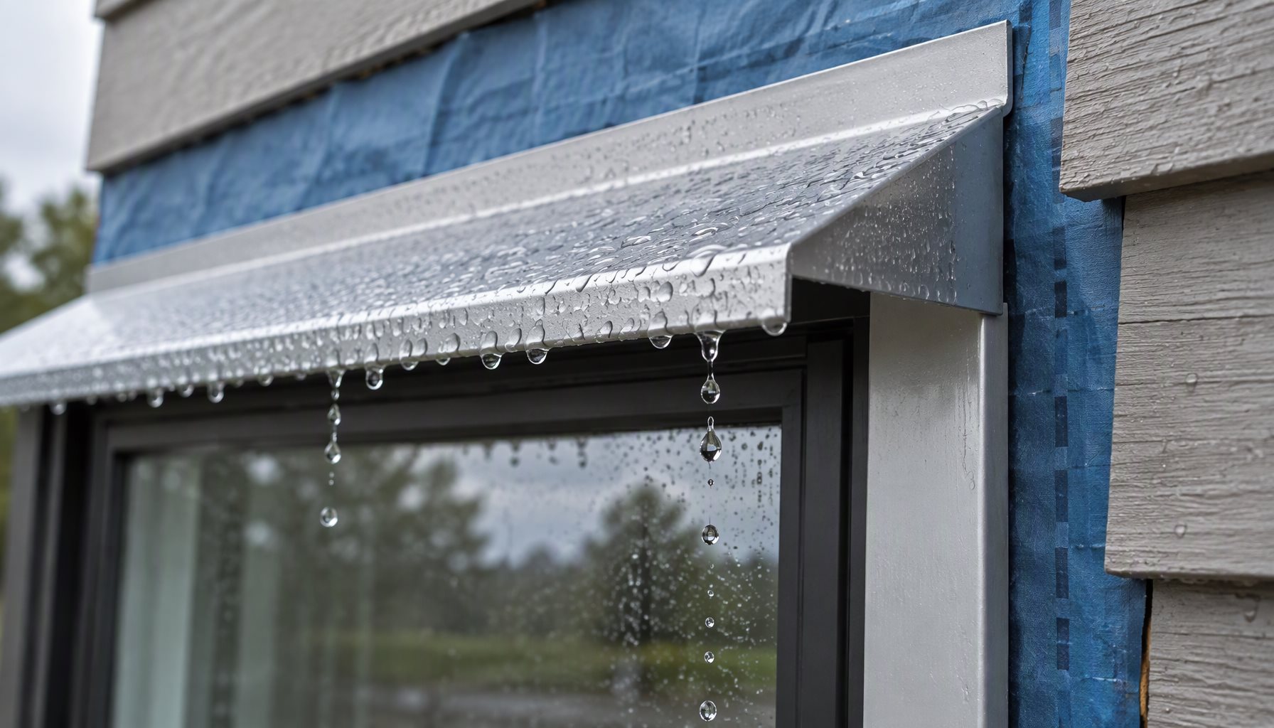
    Drip cap vs caulk: metal head flashing with a projecting drip edge shedding water clear of an aluminum window head

    Two Jobs, Two Failure Modes

    A drip cap is a formed metal profile, aluminum on most commercial and better residential work, with a sloped top surface, a projection past the face of the frame, and a drip edge standing clear of the wall below. It takes the water that lands on it and discharges it beyond the plane of the opening. It also creates a discontinuity — a break in the path a droplet would otherwise follow from the wall above, across the head joint and into the frame. Water does not climb a discontinuity.

    A seal is a joint filler. It bonds to two substrates, accommodates some movement between them, and keeps water out by staying continuous and adhered. It has no slope, projection or drip edge, and needs none, because its job is to close a gap rather than divert a flow. Its performance is a function of adhesion, joint movement, and the environment that degrades both.

    A shedder’s performance is fixed at installation; a seal’s begins degrading at installation. That asymmetry is the whole argument, and it is why a design relying on sealant at the head has already scheduled its rework.

    The Head Detail

    Water reaching a window head arrives from above, from a catchment area many times the width of the joint it drains to, and wind-driven rain is pushed against the facade and driven sideways under the smallest gap.

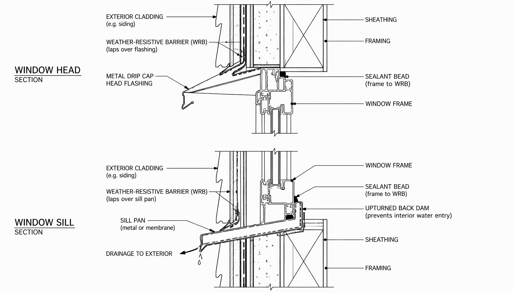
    The correct sequence, from the outside in: the weather-resistive barrier below the opening laps over the flashing; the flashing or drip cap is set over that lower layer and turned up at the back; the window is set with its head flange integrated with the flashing; the barrier above laps over the top of the flashing; the cladding goes on last. Every layer laps over the one below, so gravity carries water outward at every interface. A single reversed lap turns the head into a funnel.

    Three details decide whether the cap actually sheds:

    • Slope. The top surface has to drain. A flat cap holds water until it finds a fastener or a lap.
    • Projection and drip edge. The cap must project beyond the face of the frame, with a drip edge standing proud of the wall below. A cap flush with the cladding gives water no way to release clear of the joint; surface tension pulls the bead back against the wall.
    • End dams. At each end the flashing has to turn up, or terminate into a wall condition that stops water running sideways off the end and behind the cladding.

    Most failures sit at the interface between cap and barrier, which depends on the rough opening being square, correctly dimensioned and detailed in sequence before the window arrives. The window rough opening preparation that makes a head detail work is sequence work, not sealant work.

    Why Sealant Gets Used Where a Drip Cap Was Needed

    A tube of sealant is cheap, fast and requires no coordination. A drip cap is cheap too — the metal is not the cost — but it requires sequence: barrier, flashing, window, barrier over the flange, cladding. That sequence has to be agreed between trades, and the head is often closed before anyone checks it. On a production schedule the caulk gun is the path of least resistance, and it produces a joint that looks finished.

    Then there are the assumptions. A nailing fin or factory head flange is not a drainage detail on its own; a flange sealed to the wall with a bead, no slope and no projection is a seal pretending to be a shedder. An eave or soffit reduces exposure but does not eliminate wind-driven rain, and does nothing for a gable opening. Sealant is fine as a secondary measure at a termination, but not as the primary defense, because it is the only component whose performance is guaranteed to decline. And a head can stay dry for years in a sheltered exposure before it fails in the first storm that drives rain at the right angle.

    Sealant ends up where a drip cap was needed because the missing component is invisible after close-in, while the substitute is visible as a neat bead. That is a scheduling problem, not a materials problem.

    Drip Cap vs Caulk, Function by Function

    Drip cap vs caulk section detail: head flashing, lapped weather-resistive barrier, sealant bead and sill pan with upturned back dam
    ComponentFunction and where it goesTolerances, failure mode and service life
    Drip cap / head flashingShedder — intercepts water running down the wall and throws it clear of the head, creating a discontinuity in the water path. Set over the head, lapped into the weather barrier and under the cladding, projecting past the frame face with a drip edge.Tolerates water volume, wind-driven rain, UV and freeze-thaw, provided slope and projection are correct. Fails from installation error — reversed lap, flat slope, short projection, missing end dam, unsealed fastener, untreated cut edge. Service life: the wall assembly if installed correctly; the metal is not the limiting factor.
    Sealant at the head jointSeal — closes a joint by adhesion, keeping out water that has already reached it. Placed in the joint between frame and wall, at terminations and at joints designed to move.Tolerates movement within its stated capability, thermal cycling and wetting, for a limited period. Fails at the bond line — adhesion loss, cohesion tear, fatigue, UV and dirt degradation, hidden behind the cladding line. Service life: finite and shorter than the wall; a recurring replacement item.
    Sill pan with back damCollector and shedder — catches water past the window, slopes it out and dams it from the wall cavity. Set under the window at the sill, turned up at the back and ends, draining to the exterior.Tolerates brief standing water, debris and occasional overflow, provided it drains. Fails as a flat pan, blocked weep, or missing or discontinuous back dam — the pan becomes a tray. Service life: the assembly if it drains; fails early if it does not.

    In the drip cap vs caulk comparison, the asymmetry matters more than any single cell. The shedder’s weak points are installation errors, inspectable before the wall is closed. The seal’s weak point is time, and it cannot be inspected without opening the joint.

    The Sill Pan and the Back Dam

    The same logic applies at the sill.

    A sill pan is a collector and a shedder. It catches water that gets past the window or through the frame, slopes it to the exterior, and discharges it through the cladding or a weep path. A back dam is the upturned rear leg of that pan, and it is a discontinuity in its own right: it stops water running backward into the wall cavity. End dams do the same at the sides. The pan does not have to be watertight in the sense a seal is watertight; it has to drain.

    Sealant appears at the sill in two very different roles. As a secondary seal at the corners and at the frame-to-pan interface, it is appropriate. As the primary defense in place of a pan, it is not, and it fails destructively: water that gets past the seal has nowhere to go, so it sits against the frame, the rough opening and the wall assembly. A sealed sill with no slope and no dam is a tray. A pan with a back dam is a drain.

    How the Two Fail Differently

    Sealant fails at the bond line first. Adhesion loss shows up as a pull-away, a crack, or a bead released from one substrate while still attached to the other. Movement accelerates it: a joint cycling with thermal expansion and wind load fatigues the sealant, and once the bond breaks, water enters behind the bead and travels by capillary action. In a vertical head joint the failure is hidden behind the cladding line, so the first evidence is water inside the wall, not a visible defect.

    A metal drip cap fails differently. The material is durable; what fails is the installation or the interface — a reversed lap, a cap installed flat, a projection short of the frame face, a missing end dam, fasteners driven through the face without sealing, cut edges left untreated on a coated product. Coating performance matters at those cut edges and in coastal exposures, which is what AAMA 2605 addresses — see powder-coat durability and preventing aluminum window corrosion. Note the difference in kind: the drip cap’s failures are errors made once, at installation, and correctable before close-in. The seal’s failure is a recurring event with a service interval.

    That is why “caulk it again every few years” is not a maintenance plan. It describes a detail missing its shedder, maintained at the owner’s expense for the life of the building.

    Specifying Both

    A specification that names both components and assigns each its role settles most of the argument before installation begins.

    • Head flashing at every exterior opening. Require a sloped head flashing or drip cap with a drip edge projecting beyond the frame face, end dams at both terminations, and a back leg integrated with the weather barrier. Require the lap sequence on the drawings, not in a note.
    • Sealant by function, not by brand. Require sealant at joints that move and at terminations, and state that it is not the primary water defense at the head. Where a joint moves, the sealant has to be selected for that movement.
    • Sill pan with back dam. Require a sloped pan with a continuous back dam and end dams, draining to the exterior, in the same section as the window so it cannot be value-engineered out.
    • Compatibility. Require the sealant, flashing membrane and barrier to be compatible and specified as a system. A sealant that attacks the membrane it bonds to is a failure that starts on day one.
    • Testing references. Require water penetration resistance to ASTM E547 and mock-up testing to AAMA 501 where the project calls for it, air leakage to ASTM E283, and structural performance to ASTM E330, then confirm against the certified test data for the assembly.

    A laboratory water test runs on a complete assembly with the manufacturer’s intended detail; change the head to a bead of sealant and the rating no longer describes the wall. The quality controls that make a tested assembly repeatable in the field are part of the specification too.

    Inspecting the Detail in the Field

    Inspect after the flashing and before the cladding.

    At the head: confirm a sloped member drains away from the wall; that it projects past the frame face with a drip edge clear of the wall; that the barrier above laps over the flashing and the flashing over the barrier below; that end dams are present; that fastener penetrations are sealed; that cut edges are treated.

    At the sill: confirm slope, back dam, end dams and a clear weep path.

    At the joints: confirm sealant is present where a joint moves, that joint width and depth suit the sealant, and that substrates are clean and compatible. A bead applied over dust or a wet surface is a bead with a known future.

    A hose test at the head can expose a reversed lap, but it is not a rating. Water penetration resistance is established by ASTM E547, and AAMA 501 defines the field procedure where the project requires one.

    The practical takeaway is one question asked at the right time: what sheds the water at this head, and what only seals a joint? If the same component is doing both, the detail is wrong, and the cost will show up as a callback rather than a line item.

    Installer setting a metal drip cap head flashing above an aluminum window while a sealant bead closes the frame joint

    Frequently Asked Questions

    Drip cap vs caulk: does a window need both?

    Yes, in different roles. The drip cap sheds water away from the head and keeps the joint dry; sealant closes the joints that must move and the terminations the cap cannot cover. Neither backs up the other.

    Can I just caulk the top of a window instead of installing a drip cap?

    No. A bead of sealant holds water at the face of the joint and depends on adhesion, so it begins degrading as soon as it cures, and it has no way to discharge the volume of water that reaches a head. Sealant can supplement a head detail, but it cannot replace the shedder.

    Where exactly does the drip cap go?

    Over the window head, lapped into the weather barrier in shingle fashion and under the cladding, with the drip edge projecting past the frame face. The barrier below laps over the flashing and the barrier above laps over its top, so water always travels outward and downward.

    How often should window sealant be replaced?

    There is no universal interval; it depends on the sealant, joint movement, exposure and substrate. A predictable replacement cycle usually means the detail relies on a seal where a shedder was needed, and the correct fix is the flashing detail, not a better bead.

    What is the difference between a drip cap and head flashing?

    Head flashing is the broader term for the water-shedding layer at the head of an opening, including its integration with the weather barrier. A drip cap is the formed profile with a sloped face and projecting drip edge that does the shedding. On many details they are the same piece of metal, but the flashing function includes the laps and end dams around it.

    Lansen Windows & Doors manufactures thermally broken aluminum windows, doors, curtain walls and sunrooms in Foshan, Guangdong, and exports to North American importers, contractors and window brands. For project-specific head, sill and flashing details, or to discuss a package, request a project estimate.

  • Why Aluminum Windows Leak: 6 Causes & Fixes

    Why Aluminum Windows Leak: 6 Causes & Fixes

    Why aluminum windows leak is a question that usually has nothing to do with the aluminum. The material does not absorb water, warp under moisture or rot, so water appearing on an interior sill has almost always travelled along a path the assembly was supposed to manage — a blocked drainage route, a failed sealant joint, a compressed gasket or an installation detail that broke the weather barrier.

    This article explains how water is meant to leave an aluminum window, the failure modes that let it enter instead, and how to diagnose the actual path before ordering repairs or replacement units.

    Water beading on the sill of a black aluminum window in the rain

    Why Aluminum Windows Leak: It Is Rarely the Frame Material

    Aluminum framing is dimensionally stable and impervious to water absorption. When a leak appears, the cause sits in one of four places: the water management design of the system, the interfaces between the window and the wall, the seals and gaskets that close the moving joints, or the workmanship on site.

    That distinction matters commercially. A leak attributed to “the windows” is often a leak in the flashing, the sealant or the rough opening, and replacing units will not fix it. Knowing why aluminum windows leak at an interface rather than in the profile is what makes diagnosis fast.

    It is also worth separating water penetration from condensation. Moisture that forms on the interior glass surface in cold weather is a humidity and thermal performance issue, not a leak, and it requires a completely different response.

    Where Water AppearsMost Likely PathFirst Check
    Interior sill, near the cornersBlocked or missing weep drainageWhether weep openings are clear and the sill drains outward
    Along the head of the frameHead flashing or sealant failure above the unitContinuity of flashing and condition of the perimeter sealant
    At the jamb, mid-heightPerimeter seal or shim gap left openSealant adhesion and whether the shim space was closed out
    Around the operating sashCompressed, aged or misaligned gasketGasket compression and sash alignment against the frame
    Only during wind-driven rainPressure differential across the assemblyDrainage path and whether the system suits the exposure

    How Water Is Supposed to Leave an Aluminum Window

    A properly designed fenestration system does not assume water will be excluded entirely. It assumes some water will get past the outer line of defense and provides a controlled route for it to leave.

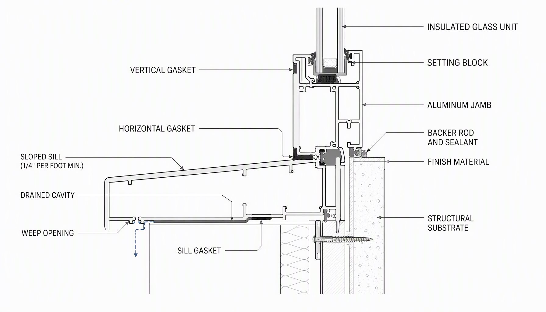
    The key elements are a sloped sill that sheds water outward, weep openings at the low points, a drained cavity where the system uses one, and sealed inner lines that stop air and water moving inward. When weeps are blocked by sealant, debris, screening or paint, water that would have drained accumulates and finds another route. Standing water in the sill is also the starting point for most finish and pitting complaints, so preventing aluminum window corrosion treats drainage maintenance as a corrosion control, not a cleaning task.

    These behaviors are measured rather than assumed. ASTM E283 / E283M determines air leakage rate through a specimen under a stated pressure differential, and ASTM E331 addresses water penetration under static pressure differential. Both are test methods, not ratings: a rating is the result a specific specimen achieved under defined conditions. FGIA publishes the AAMA standards and field test methods commonly used to evaluate installed assemblies.

    Cutaway technical diagram of an aluminum window sill and jamb junction showing sloped sill, drained cavity, weep opening and gasket lines

    Installation, Flashing and Tolerance Failures

    Most reported leaks originate at the interface between the window and the wall rather than in the window. Common installation-related causes include:

    • Flashing not integrated with the weather barrier. Head flashing, sill pan and jamb details must shingle in the correct order so water is directed outward.
    • Sealant used as the primary water barrier. Sealant is a secondary line of defense; where it is the only one, any loss of adhesion becomes a leak.
    • Open shim gaps. Shim space left unclosed creates a direct path from exterior to interior.
    • Out-of-square or undersized rough openings. Forced fitting distorts the frame and stops gaskets compressing evenly.
    • Unsupported sills. A sill that flexes under load breaks its own sealant bond.

    Rough opening accuracy underpins all of these. Our window rough opening guide explains how openings are measured and verified across wood, masonry and concrete substrates.

    Fastener choice matters too. Aluminum does not rust like steel, but it can corrode in aggressive environments, particularly where dissimilar metals contact without isolation. Galvanic separation, compatible fasteners and correct coating specification belong in the assembly design.

    Gaskets, Sealants and Hardware Degradation

    Moving joints are sealed by compression gaskets or brush seals, and those components age. Ultraviolet exposure, temperature cycling and repeated operation reduce elasticity over time, so a gasket that no longer returns to shape stops compressing — and an uncompressed gasket does not seal.

    Sealant fails in recognizable ways: loss of adhesion at one substrate, cohesive tearing, hardening and cracking, or three-sided adhesion that prevents the joint moving with the building. Joint width and depth relative to expected movement must be specified deliberately, because sealant in an undersized joint fails regardless of product quality.

    Hardware contributes indirectly. A dropped sash, a worn roller or an out-of-adjustment operator changes the geometry of the closing line so the gasket no longer meets its intended compression. Operational problems frequently present as water problems.

    Thermal movement adds another variable: aluminum expands and contracts more than glass or masonry, so a wide frame in strong sun moves relative to its surrounds. Joint design has to accommodate that movement rather than resist it.

    Diagnosing a Leak Before Ordering Repairs

    Work outward from the evidence. Confirm whether water is entering under calm rain or only under wind, note exactly where it appears inside, and check the drainage path before touching any seal.

    Test MethodWhat It MeasuresWhat It Does Not Prove
    ASTM E283 / E283M (laboratory)Air leakage rate through a specimen at stated pressurePerformance of a different size, glazing or configuration
    ASTM E331 (laboratory)Water penetration under static pressure differentialBehavior under dynamic wind and rain in the field
    ASTM E330 (laboratory)Structural response to uniform static air pressureWatertightness of the installed wall interface
    Field water spray testing (AAMA/FGIA methods)Whether the installed assembly leaks in placeWhich component is at fault — it locates, not explains
    Visual and borescope inspectionDrainage condition, sealant state, gasket compressionRate of leakage or design pressure capability

    A test report for one specimen does not automatically prove performance for every size or configuration in the same family, and no laboratory result predicts what happens once a unit is installed in a specific wall. Field investigation and laboratory evidence answer different questions.

    Model code requirements for the surrounding wall assembly are maintained through the International Code Council. The edition adopted by the jurisdiction governs, and local amendments frequently add wind-driven rain provisions.

    Project RequirementRecommended ChoiceWhy
    Isolated leak at one openingInspect drainage and perimeter sealant firstLocalized symptoms usually indicate a localized path, not a system defect
    Leaks across many openings on one elevationTreat it as a design or workmanship patternRepetition points to a detail, an exposure mismatch or a shared installation error
    Leak only in wind-driven rainReview system suitability and pressure managementStatic-condition performance does not represent dynamic exposure
    Moisture on interior glass in cold weatherAssess as condensation, not infiltrationDifferent cause, different remedy — see thermal break windows
    Aged gaskets, sash misalignmentRe-gasket and re-adjust before replacing unitsRestoring compression often resolves infiltration at a fraction of replacement cost
    New build in exposed coastal locationSpecify tested evidence matched to design pressureExposure sets the requirement; the product must be shown to meet it

    Uncontrolled air movement also affects energy performance, which is why U.S. Department of Energy guidance treats air leakage and thermal performance as linked issues.

    Technician inspecting the sill and jamb of a large aluminum window in a commercial building during rain

    Frequently Asked Questions About Why Aluminum Windows Leak

    Why aluminum windows leak when the frame itself does not absorb water?

    Because the leak is almost never in the aluminum. Water enters through drainage paths that are blocked, seals that have aged, interfaces between window and wall that were not detailed correctly, or gaskets that no longer compress. The frame material is the most durable part of the assembly.

    Are blocked weep holes a common cause?

    Yes, and they are frequently the first thing to check. Weep openings let water that has entered the drained cavity exit to the exterior. When they are obstructed by sealant, debris, paint or screening, water accumulates and migrates inward instead of draining outward.

    Is the leak the window’s fault or the installer’s?

    That has to be established by investigation, not assumption. Water at the head of the frame usually implicates flashing above the unit; water at the jamb implicates perimeter sealing and shim gaps; water around the sash implicates gaskets and alignment. Field water spray testing locates the leak but does not by itself assign cause.

    Can a leak only happen in wind-driven rain?

    Yes. Wind creates a pressure differential across the assembly, and that differential drives water through openings that calm rain would not penetrate. Laboratory water penetration testing under static pressure and field spray testing under dynamic conditions measure different things, so passing one does not guarantee the other.

    Will resealing the outside perimeter fix it?

    Sometimes, but not reliably. If the drainage path is blocked, adding sealant traps water inside the assembly and can make the problem worse. Clear the drainage route and identify the entry path first; sealing is a secondary measure, never the primary water barrier.

    Do leaks mean the window is not energy efficient?

    Not necessarily, though the two are related. Uncontrolled air movement through an assembly affects both infiltration and heat loss, and a distorted frame from installation stress can degrade both. Thermal performance ratings and watertightness are established separately, so one is not evidence of the other.

    How does condensation differ from a leak?

    Condensation forms on the interior surface when warm humid air meets a cold surface, typically on glass in winter. A leak is liquid water entering from outside, usually at a frame or wall interface. Condensation is a humidity and thermal issue; a leak is a water management issue. Confirming which one is present determines everything that follows.

    Request a Leak Diagnosis and Specification Review

    If you are dealing with water ingress on a project, send photographs of the affected openings, the elevation and exposure, the system type and any existing test documentation. Our engineering team can review the drainage design, gasket and sealant specification and installation interface details, and advise whether the issue sits in the product, the wall assembly or the workmanship. Our quality and testing page explains the documentation we provide, and the window hub and contact page are the fastest routes to a technical review.