Large sliding doors are structural assemblies, not bigger versions of standard ones. Beyond roughly 2.4 m (8 ft) in height or 1.8 m (6 ft) in clear panel width, three relationships take over: wind pressure acts on a much larger area, frame deflection grows with the fourth power of the span, and panel weight becomes a mechanical load on the track, rollers and floor structure.
The requirements that decide performance follow from those: design for the project wind pressure from ASCE 7 and qualify to ASTM E330; keep header, jamb and track deflection inside limits that preserve operation and seal compression; size the glass for the panel span; carry the panel weight through the track, rollers and anchorage; and complete a continuous load path through the interlock, jamb and head.
This article covers the structural layer of large sliding doors. It does not repeat the dimensional schedules, hardware options or replacement guidance in our sliding glass door specifications, standard sliding door sizes and replacement sliding glass door articles; it assumes the opening is sized and asks what the frame, glass and anchorage must do. Figures are typical ranges, not guarantees; where a value depends on the tested assembly, confirm against its certified test data.
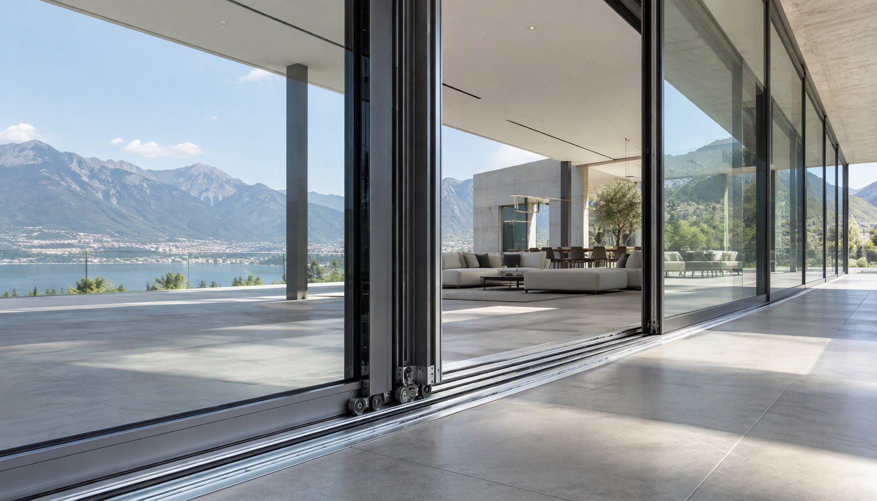
What Changes When a Door Gets Large
Wind load is pressure times area, so it rises linearly: a 3.0 m × 2.4 m panel carries four times the load of a 1.5 m × 1.2 m panel at the same pressure. Deflection is harder. For a header of fixed section and load per unit length, deflection varies with the fourth power of the span, so doubling the span multiplies it by sixteen. Weight rises linearly with area, but roller capacity comes in discrete sizes, so hardware steps up in jumps.
Tolerances accumulate too: a 6 m track must be flatter and straighter than a 2 m one, and thermal movement across a long head must be absorbed without loading the jambs.
Design Wind Pressure: The Load That Sizes the Assembly
The starting point is the design wind pressure, not the door. ASCE 7 gives components-and-cladding pressures that vary with risk category, exposure, height and position on the facade; corners, parapets and upper floors see substantially higher pressures than the middle of a wall. For North American low- and mid-rise work, design pressures commonly fall between 25 and 50 psf (1.2 to 2.4 kPa), with high-rise and exposed coastal sites higher. Use the project’s own ASCE 7 calculation; FEMA’s wind-design resources explain how the maps and exposure categories feed it.
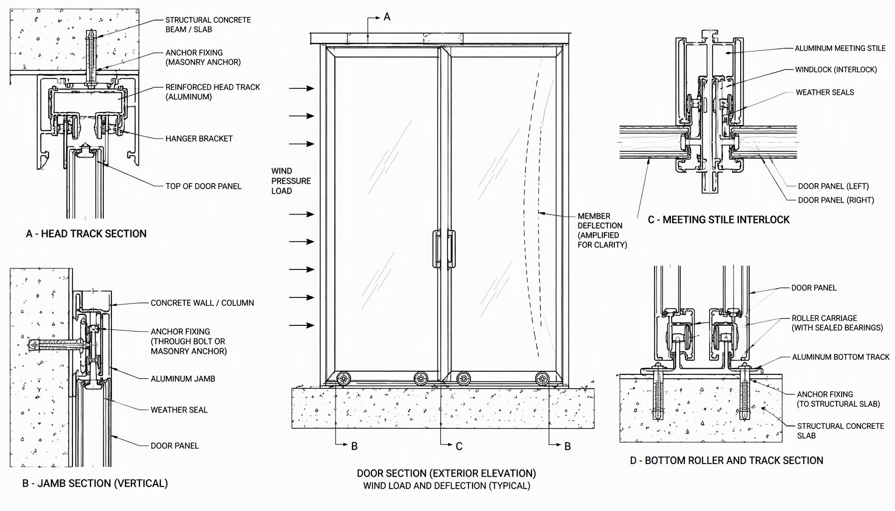
State both positive and negative pressure, because a sliding panel behaves differently in each direction. Under positive pressure it bears on the track and sill; under suction it lifts and pulls on the rollers, head guide and interlock. Windlocks or anti-lift details are not optional on large panels.
Qualification is by test on the complete assembly: ASTM E330 for structural performance at the specified design pressure, ASTM E283 for air leakage, ASTM E547 for water penetration. In windborne-debris regions, ASTM E1886 and ASTM E1996 apply to impact and cyclic pressure, which usually pushes glass to laminated construction — see impact-rated sliding doors for that layer. The result belongs to the tested assembly, so a report for a smaller door does not qualify a larger one.
Deflection Limits and Why They Govern Panel Size
Deflection, not stress, usually sets the maximum panel size. Aluminum extrusions rarely fail in bending at service wind loads; they bend enough to bind panels, lose gasket compression and crack seals long before yield.
North American specifications commonly limit glass-supporting and door-framing members to L/175 of the span, moving toward L/240 with an absolute cap on longer spans; many also cap total deflection at 19 mm (3/4 in). Those are conventions, and the project criterion governs. Apply the limit to the member that actually spans — head track, jamb or structural header.
A head that sags under panel weight changes roller clearance, and most carriages allow only a few millimetres of vertical adjustment; beyond that the panel drags on the sill. A jamb that deflects under wind loses gasket compression at the edge where water first enters. A frame that racks out of square will not meet its interlock cleanly, so load transfers into the meeting stiles.
The Two Deflection Checks That Get Missed
Vertical deflection of the head under dead load is a creep problem as much as an elastic one, and worse on wide openings. The second is deflection of the supporting structure: slab live-load deflection and drift must be kept out of the frame by a movement joint at the head, or the frame inherits movements it was never detailed for.
Glass Specification for Large Sliding Door Panels
Glass thickness follows from panel span and design pressure; it is calculated, not picked by area. As a working range, monolithic tempered glass from about 6 mm to 12 mm covers most panels up to roughly 4 to 5 m². Where the panel must stay in its opening after breakage — impact regions, overhead glazing, high-traffic entrances — laminated glass is specified, typically 6/6, 8/8 or 10/10 mm lites with a PVB or ionoplast interlayer. Insulating glass units suit thermal performance; NFRC 100 ratings describe that performance, not structural capacity.
Edge support decides whether the thickness is usable. The glass must be retained with a continuous gasket or structural silicone, set on blocks that carry the panel weight without point-loading the edge, and given edge clearance for thermal and structural movement. Bite depth is typically 12 to 20 mm, and the detail must let the glass deflect without touching frame or bead.
Laminated Versus Monolithic
Monolithic tempered glass is stronger undamaged and cheaper per square metre. Laminated glass keeps the opening closed after breakage, which matters for a door people walk through, and it is usual where ASTM E1886 and ASTM E1996 apply. Laminated units are heavier, returning the problem to the track and rollers, and less stiff at equal thickness, returning it to deflection. Where the door is part of a tested assembly, the make-up in the specimen is part of the qualification, so confirm against the certified test data before substituting.
Panel Weight, Track and Rollers
Glass weighs roughly 2.5 kg/m² per millimetre of thickness: an 8 mm lite is about 20 kg/m², a laminated 8/8 unit about 40 kg/m², and an insulating unit with two 6 mm lites about 30 kg/m². A 3.0 m × 2.4 m panel with laminated glass lands near 300 kg, and the frame, rollers and track must be detailed for it.
Roller assemblies are rated per pair or per carriage, and the rating is a working load, not a proof load. Large panels commonly need two or more carriages, a tandem arrangement, or a top-hung system that takes the weight into a structural head. Catalog ratings assume a flat, straight, correctly anchored track; a track out of level by a few millimetres concentrates load on one carriage and shortens its life.
The track is itself a structural member. It must be continuously supported, anchored into a structural embed or steel member rather than floor finish or screed, and its anchorage must take the vertical point loads at each roller as well as the horizontal wind load. On suspended slabs, the slab edge or beam needs checking for those loads.
The sill must also drain: weeps are easily blocked when a heavy panel sits over them, and standing water at a sliding track is a common complaint.
Anchorage and the Load Path
Every load has to reach the structure through a defined path: panel to interlock and stiles, stiles to jambs and head, jambs and head to anchors, anchors to the structural frame. That path is only as strong as its weakest connection, usually the anchor into the substrate.
Anchorage design starts with the substrate. Cast-in embeds or chemical anchors into structural concrete behave differently from power-actuated fasteners into a slab on grade. Edge distance, embedment, concrete strength and post-tensioning all change capacity, and the anchor manufacturer’s published values for the base material are the only defensible basis for selection. At a slab edge, anchors work in tension as well as shear, and wind load on a deep jamb creates a moment that must be resolved.
Connections should be slotted or otherwise detailed for movement. Long aluminum jambs and heads move with temperature, and the structure moves with live load and drift; if both ends are fixed rigidly, the frame bows or cracks its seals.
Interlock, Jamb and Head Details
The interlock is a structural joint, not a weatherstrip. When wind pushes on one panel, the meeting stiles bear against each other through the interlock. If engagement is short or clearance loose, the panel racks and load goes into the rollers and jamb instead. Typical engagement for a heavy commercial interlock runs 15 to 25 mm, with a hooked or box profile resisting movement both ways.
At the jamb, the panel needs a pocket deep enough to be plumbed and shimmed while still leaving gasket compression. Too shallow forces the installer to plane the frame or omit the gasket; too deep leaves the panel bearing on a thin shim at one point. The jamb also carries wind load from the panel edge, so anchor spacing follows the load rather than a preferred rhythm of fixings.
At the head, the guide track and windlocks keep the panel engaged under suction and stop it lifting out. The detail must allow vertical adjustment after the panel is hung, because glass weight deflects the head and track, and the panel has to be set to the deflected condition rather than the theoretical line. At the sill, the track must be level and parallel to the head, with drainage clear and the bearing surface continuous under the rollers.
How the Governing Constraint Changes with Opening Size
The table summarizes which constraint typically governs as large sliding doors grow. It is a planning guide, not a substitute for project engineering.
| Panel size band | Governing constraint and the structural check that decides it | Typical specification response |
|---|---|---|
| Up to about 2 m² (e.g. 2.1 m × 0.9 m) | Glass thickness and standard hardware govern; header deflection at L/175 and roller rating against panel weight decide it. | 6 mm tempered glass; standard carriages; track anchored into structural slab |
| 2 to 4 m² (e.g. 2.4 m × 1.5 m) | Header deflection and gasket compression govern; deflection of head and jamb at design wind and panel weight against carriage rating decide it. | 8 to 10 mm glass; two carriages or heavier rollers; reduced jamb anchor spacing |
| 4 to 6 m² (e.g. 3.0 m × 1.8 m) | Wind load on the panel and interlock engagement govern; ASTM E330 qualification at design pressure and interlock and windlock capacity decide it. | 10 to 12 mm or laminated glass; reinforced head; anti-lift guides |
| Above about 6 m² or over 3 m wide | Overall load path and floor structure govern; anchorage and slab or steel capacity for combined wind and dead load decide it. | Project-specific structural design; top-hung or multi-carriage system; movement joint at head |
A specification that will control the door should state the design wind pressure in both directions and the standard used to derive it; the deflection limit and the members it applies to; the qualification tests required, applied to the proposed assembly at the proposed size; glass make-up, edge support and bite; panel weight, roller rating and track anchorage; and interlock engagement, windlocks and the head movement joint. Field verification using AAMA 501 methods catches the installation errors no drawing can prevent.
Frequently Asked Questions
What wind load should large sliding doors be designed for?
It depends on the project. ASCE 7 components-and-cladding pressures vary with risk category, exposure, height and facade position; typical North American low- and mid-rise values run about 25 to 50 psf, with exposed and high-rise locations higher. Use the project’s own calculation, state both positive and negative pressure, and confirm the assembly against certified test data at that pressure.
What deflection limit applies to a sliding door header?
Many North American specifications use L/175 of the span for glass-supporting and door-framing members, moving toward L/240 on longer spans, often with an absolute cap such as 19 mm. The project criterion governs. Apply it to the member that actually spans. Deflection must also stay inside the roller adjustment and gasket compression ranges.
How thick should the glass be in a large sliding door?
Thickness is calculated from the panel span and the design pressure, not chosen by area alone. Monolithic tempered glass from about 6 mm to 12 mm covers most panels up to roughly 4 to 5 m², with laminated 6/6, 8/8 or 10/10 units used where the panel must stay in its opening after breakage. Have the glazing engineer confirm the make-up for the actual panel size and pressure.
How much does a large sliding panel weigh?
Glass weighs roughly 2.5 kg/m² per millimetre of thickness, so a 3.0 m × 2.4 m panel with laminated glass is around 300 kg before frame and hardware. That figure drives the roller rating, the number of carriages and the track anchorage. Confirm the actual weight from the shop drawing rather than estimating from area.
Can a large sliding door be anchored to wood or cold-formed framing?
Only with an engineered connection. The combined wind and dead loads usually exceed what light framing or sheathing can take in tension, so blocking, a steel member or a concrete embed is normally required. Anchor capacity must come from published values for the base material, and the substrate must be checked by the structural engineer of record.
Large sliding doors are decided by the load path, not the profile. Lansen manufactures thermally broken aluminum sliding doors, windows and curtain walls in Foshan for North American commercial projects, and reviews panel sizes against design pressure, deflection and hardware capacity before shop drawings are released. Send the elevations, panel sizes and design pressures, and we will return a structural review of the proposed assembly. Contact our engineering team to start that review, or see our documented quality assurance procedures.